Surge Protection For Wind Generation Facilities

- Prosurge
- China
- Within 25 days
- 5kpcs per month
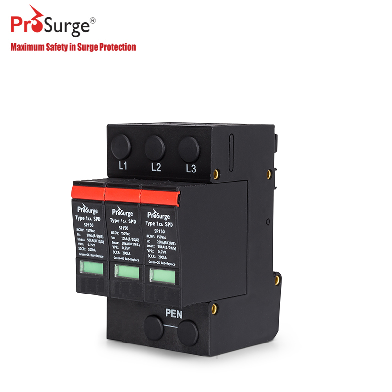
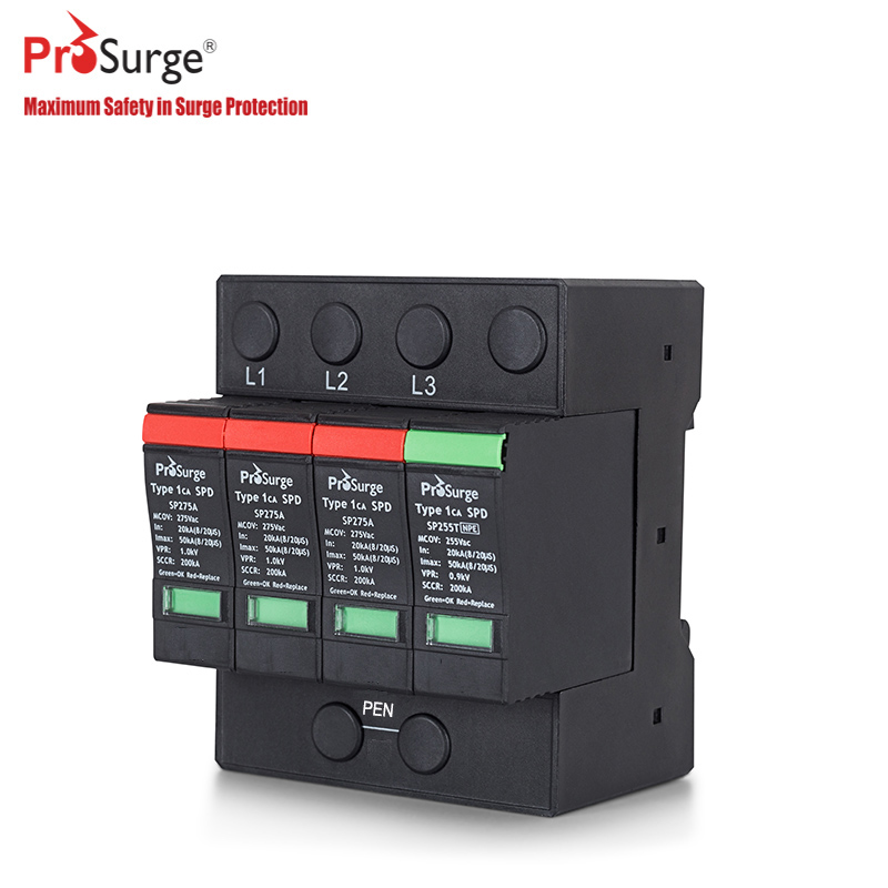
Type 2/Class II surge protective device is designed for low-voltage power supply system protection against surges at the boundaries from lightning protection zone 1-2 and higher.
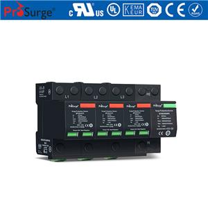
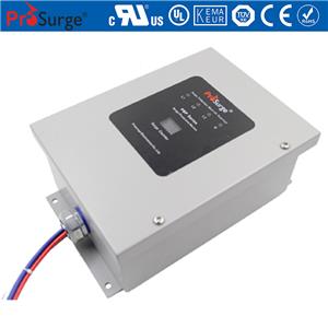
Pluggable T2 SPD with high energy MOV technology for wind turbine
High reliability due to global patented thermally protected with special arc-extinguish device (TPAE technology)
High surge current discharge capacity up to 40kA 8/20μs
Pluggable module for easy replacement
Degradation indication & optional remote signal contact.
Prewired for three phase 3W+G network systems such as TN-C etc
Comply with IEC/EN 61643-11, UL 1449 4th, IEEE C62.41, CSA C22.2
Surge Protective Devices (SPDs), intended to afford protection from electrical surges and spikes, including those caused directly and indirectly by lightning, are utilized as both complete devices and as components within electrical equipment installed in AC and DC power applications.
Wind turbine converts the wind's kinetic energy into electrical energy. . Arrays of large turbines, known as wind farms, are becoming an increasingly important source of renewable energy and are used by many countries as part of a strategy to reduce their reliance on fossil fuels.
Wind turbines are tall, isolated towers composed of sensitive electronics, all of which are factors that make lightning a persistent and real threat. A properly installed lightning protection system, however, will intercept the lightning and effectively and safely conduct it to the earth without risking physical destruction to the wind turbine. This issue has become increasingly critical as wind turbine systems become more sophisticated and vulnerable to lightning, and that lightning dangers will increase with turbine height.
According to the updated National Fire Protection Association (NFPA) handbook:“While physical blade damage is the most expensive and disruptive damage caused by lightning, by far the most common is damage to the control system”. In Wind turbine system, there are many vulnerable electronics equipments which be damaged by lightning strikes or and transient over-voltages, such as:
· The control system, include sensors, actuators, and the motors for steering the equipment into the wind etc.
· The electronics, include transformer, frequency converter, switchgear elements, and other expensive, sensitive equipment.
· And Generators, battery subsystem etc.
Properly installed surge protective devices (SPDs) will minimize the potential impact of lightning events,
Main reference
UL96A: Standard for Installation Requirements for Lightning Protection Systems
UL 1449 4th: Standard for Surge Protective Devices
IEC 61643-11: Low-voltage surge protective devices - Part 11: Surge protective devices connected to low-voltage power systems - Requirements and test methods
IEC 61400-24:2010 Wind turbines - Part 24: Lightning protection
Model | SP440/3P-S | SP760/3P-S | SP860/3PT-S | |
Compliance | EN/IEC 61643-11, UL 1449th | |||
Category EN/IEC/UL | T2/ Class II /Type 1ca | |||
Nominal Voltage | Un | 400/690Vac | ||
Max. Continuous Operating Voltage (AC) | Uc | 440V | 760V | 860V |
Technology | High energy MOV technology; TPAE technology (patented) | High energy MOV & GDT technology; TPAE technology (patented) | ||
Ports/Protection Mode | 1 / L-PEN | |||
Nominal Discharge Current (8/20μs) | In | 20kA | ||
Max. Discharge Current (8/20μs) | Imax | 40kA | ||
Voltage Protection Level | Up | £2.4kV | £3.0kV | £4.0kV |
Voltage Protection Level @ 5kA | Ures | <2.0kV | <2.0kV | <2.5kV |
Temporary Overvoltage TOV —Withstand Mode | Utov | 582V/5s | 900V/5s | 1200V/5s |
Residual Current | IPE | <0.1mA | <0.1mA | No |
Follow Current | If | No | ||
Short Circuit Current Rating per UL 1449 | Isccr | 200kArms | ||
Response Time | tA | £25ns | ||
Backup Fuse (only required if not already provided in mains) | 125A gL/gG | |||
Environment | Temperature Range: -40ºC ~ +80ºC; Humidity: £95%; Altitude: £3000m | |||
Cross-Section of Connection Wire | Single-strand 35mm2; multi-strand 25mm2 | |||
Mounting | 35mm DIN-rail in accordance with EN 50022/DIN46277-3 | |||
Enclosure Material | thermoplastic; extinguishing degree UL94 V-0 | |||
Degree of Protection | IP20 | |||
Installation Width | 3 modules, DIN 43880 | 4 modules, DIN 43880 | ||
Failure Indication /Status | RED- Failure | |||
Remote Alarm Contact | Yes | |||
Approvals, certification | CE | |||
Diagram | 1 | 1 | 2 | |
Additional Data for Remote Alarm Contacts | ||||
Remote Alarm Contact Type | Isolated Form C | |||
Switching Capability Un/In | AC: 250V/0.5A; DC: 250V/0.1A; 125V/0.2A; 75V/0.5A | |||
Max. Size of Connecting Wire | Max. 1.5mm2 (or # 16AWG) | |||
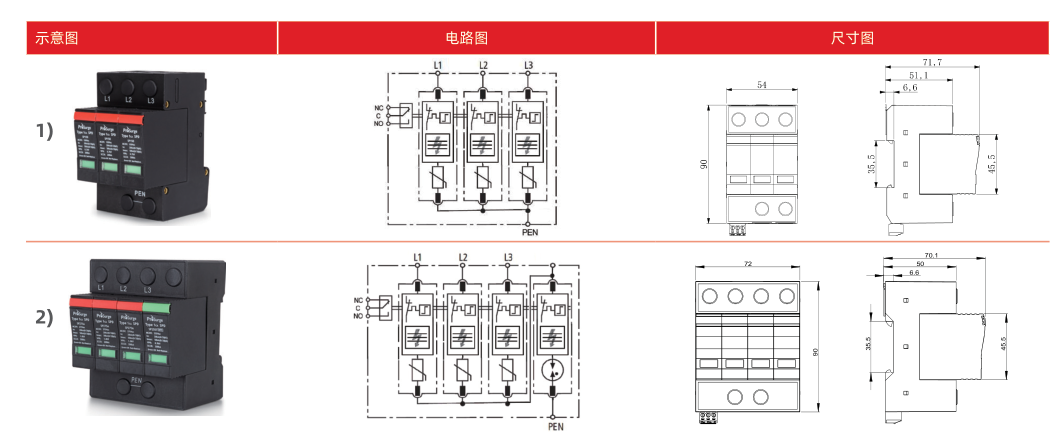
Note: SP860/3PT-S is specifically designed for protecting the rotor winding of the generator and the supply line of the inverter. An additional spark gap module is used for potential isolation and to prevent that the MOV based modules operate prematurely due to high voltage tolerances and voltage fluctuations.

